
The heart of my new(ish) darkroom control unit:

First lets get the code out of the way: darkroomcontrol-1.2 sketch
Disclaimer: For this project i worked with mains power with the potential of introducing a short circuit that may damage my equipment and the potential to incur possibly life threatening injuries! Do not attempt to do any of this yourself unless you have the proper knowledge and know what you are doing! If you have any doubt, do consult a qualified electrician before doing anything with mains power yourself!
The outside of the switchbox:
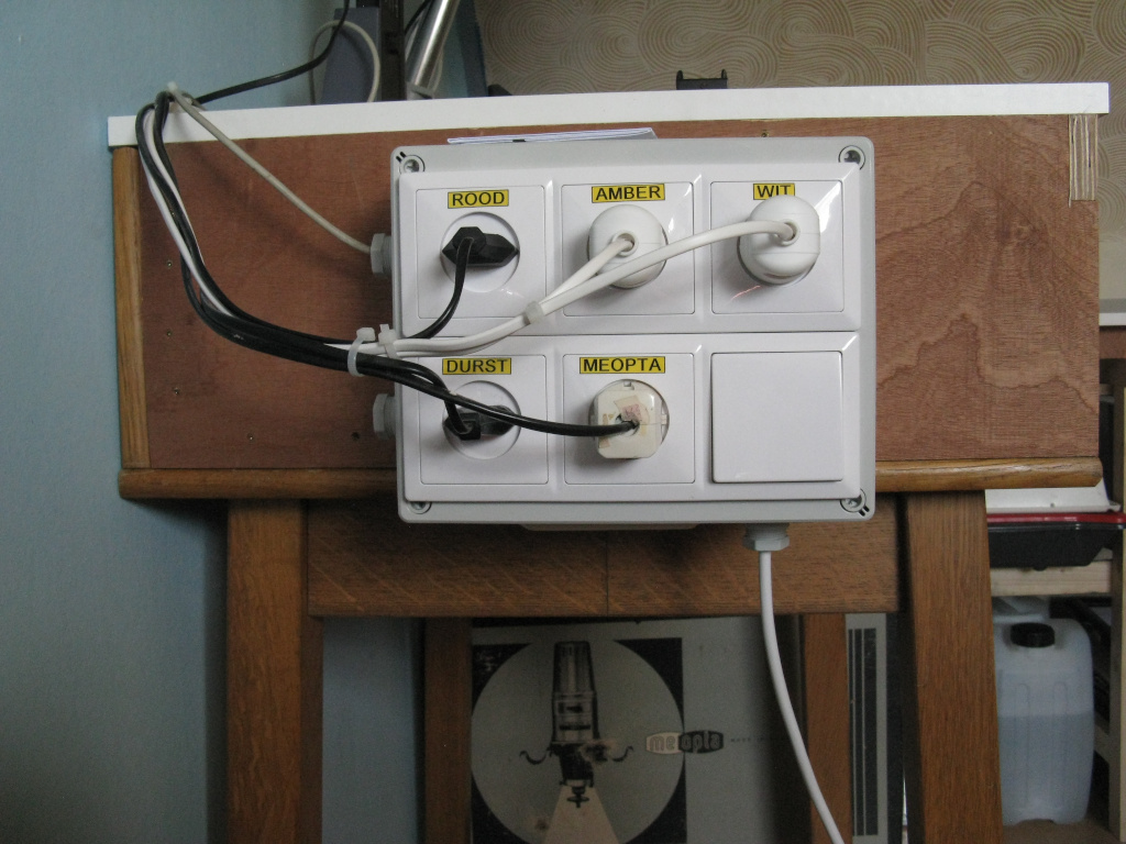
At the bottom right the master switch with underneath the power cord to the wall socket. For my darkroom lights each a seperate socket and also for both enlargers. Having markers on them is just my external memory
and the inside:

I try to keep as much seperation as possible between the mains power and the logic level power
the relay board in detail:

the power suply unit on the left delivers the +5V via the I2C port expander to the relays and the supporting transistor board. The transistors accept the low current logic levels and provide the driving power for the relays. The grey cable is a repurposed usb cable (ie cheap shielded cable) and connects the port expander to the control unit. Providing the +5V to the control unit and facilitate the I2C connection.
The transistor schematics:
![]()
The controlbox:
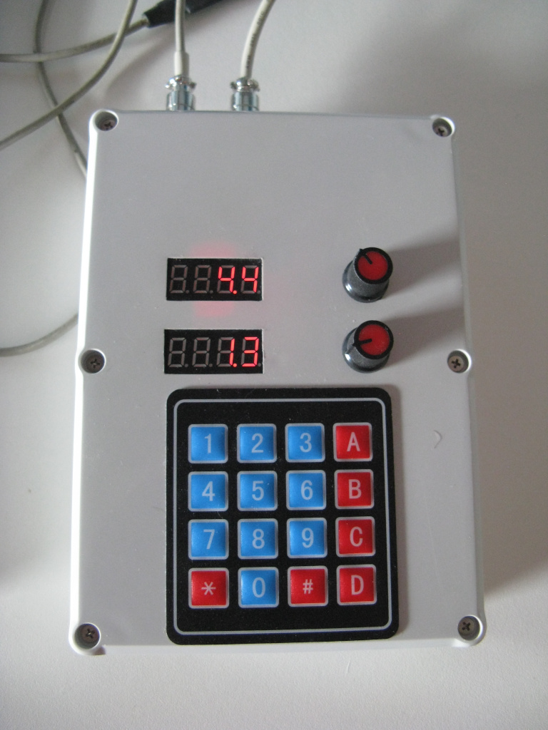
with its internals looking like this:

Here i try to keep the power wires as far away from signal wires as possible. Both displays get the power from one side of the box while the signal wires go to the other side. The green cables are shielded and take the I2C port of the arduino compatible to the outside world via 2 sockets in the housing. The black cable extends the USB connection of the arduino compatible for easy reprogramming. The control box does not need a seperate power supply as that is covered by the cable to the switchbox No fancy supporting electronics happening here, just 2 potentiometers connecting to ADC ports of the Arduino compatible, 2 x 4 segment led displays (with TM1637 controller on board) also directly connected and a 4x4 matrix keypad
the wiring underneath the arduino compatible:

On the circuit board there is seperation between power and signal as well. power wires go underneath the circuitboard